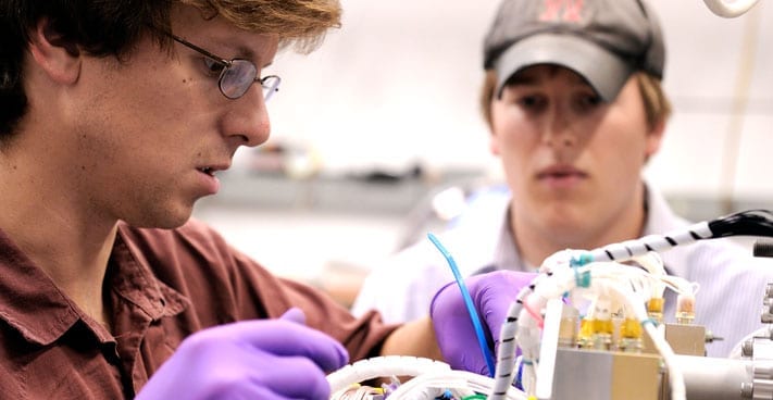
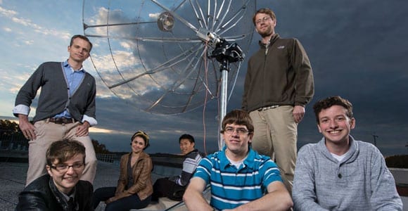
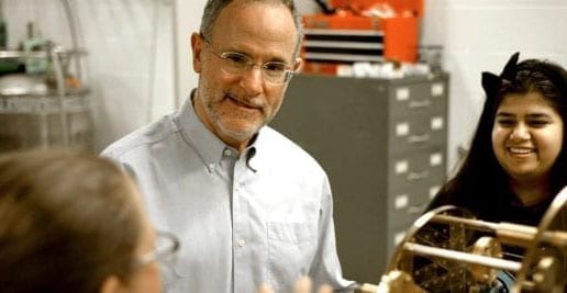
4. Optical Assessment

4.1 Introduction

The Optics Assessment Team was asked to identify methods that appear feasible to enhance HST to an eight-meter class observatory; and, select one configuration for a Feasibility Reference Mission (FRM) limited to the extent necessary to confirm, or deny, feasibility and establish a budgetary cost estimate; keeping in mind the two key science goals of identifying the era of initial galaxy formation, and imaging extra-solar, Earth-like planets.

The key to optical detection of a planet in reflected light is an aperture sufficient to place the planet at least five Airy rings distant from the star. Only then can coronagraphic and apodization techniques achieve adequate suppression of diffraction, given the expected contrast ratio of 1000 for a solar-system twin. At 10 parsecs, a one-AU orbit gives a maximum angular separation of 0.1 arcsec, placing it at the eighth Airy ring.

Detection at such high contrast ratios also requires control of wavefront aberrations to very high accuracy. Depending on the stability of the optical aberrations, they must be controlled to an error of no more than 0.1 - 1 nm rms. Such control can be realized by a combination of the basic active-mirror servo and higher order, low-amplitude correction at a deformable mirror. One alternative is to incorporate, in a single new radial-bay instrument, all the features of the basic wavefront sensing for the primary-mirror servo and the coronagraphic and higher-order correction optics. Active Line-of-Sight (LOS) detectors could be in either a modified Fine Guidance Sensor (FGS) or a new axial Science Instrument (SI) to provide an error signal. The field-of-view (FOV) of the FGS is larger than the SI so it may be preferred for this application. Including this capability in both an FGS and a new SI may be the most prudent approach by providing a backup capability.

We recognize that while imaging terrestrial planets is possible, given good enough wavefront control, the correct strategy may not be understood until the spatial and temporal character of the residual aberrations are measured on orbit. They depend on a complex interaction of the entire system. But here the essential character of the HST, the capability for servicing missions, is a huge advantage. It will be possible to learn and evolve the required processes.

4.2 Mirror Design Selection

Several mirror designs were considered. The round, two-fold design was selected for the feasibility reference mission but, depending on the material selected for flight, other designs could be considered. The round two-fold design will have the best optical performance, especially with 5000 actuators on the back plane. A ray-trace diagram of the "add-on" telescope is shown in Figure 4.1. The two-fold concept is shown in Figure 4.2.

There are about 5 or 6 good mirror materials that could be considered for this job:

  1. C/Sic built by IABG in Munich: will probably come in at about 15 Kg/square meter after clad and polish. The maximum size available will drive selection of the Hex-segment or Petal design. The CTE is not as good as Zerodur at the essentially room-temperature HST environment.
  2. COI makes a thin glass (Zerodur or ULE) face sheet with a Graphite Epoxy backing structure glued on. It is not possible to make the CTE of the two materials match all the way to cold temperatures but this approach should work fine at the room temperature expected for HST. This technology also comes in at about 15 Kg/square meter and could have actuator control as required for coarse corrections.
  3. Ball and probably others have developed very light weight (10-12 Kg/square meter) mirrors made of beryllium (Be). These would be clad and polished similar to the Secondary Mirror of the VLT. Again the maximum size limit of about 2 meters will drive the design to a Hex-segment or Petal configuration.
  4. Kodak has a water-jet light-weighting technique, which we may want to consider. It will probably weigh around 25 Kg/square meter, but can be made in one big piece with the two-fold design. Very few actuators would be required with this design.
  5. The University of Arizona (UA) design selected for this study will weigh between 15 and 20 Kg/square meter, have about 5000 correcting actuators, and use the existing VLT spare mirror blanks. The round design can be built in the existing UA facility, which has built several 8-meter mirrors, or could be done by REOSC or Contraves. The grind and polish of this 8-meter mirror would be done just like any of the ground-based mirrors such as VLT, Subaru, or Gemini. Once the mirror is polished it will be turned over onto a fixture that will support the mirror while all but 2 mm of glass is ground away. The 5000 actuators add complexity but have a nice advantage of being able to control wavefront and in the case of the Secondary Mirror, control line of sight. The schedule includes a plan to build dummy mirrors out of Borosilicate for initial test to save schedule and minimize risk to the flight mirrors. Others can do the initial grind on the VLT blanks while UA is working on the test-dummy.
 

Figure 4.1 Ray-trace of "add-on" telescope           .
Ray Trace of afocal, "add-on" telescope
4.3 Optical Assessment Overview

The notion of removing the existing Secondary Mirror (SM) was rejected early since it would require astronauts to cut away part of the existing support structure. This would result in a high probability of debris contamination and worse, it would leave HST useless in the event of catastrophe.

The selected approach does not affect the existing telescope optically or structurally; therefore, if there is a problem during the installation, the existing HST capability can be maintained up until the New Secondary Mirror (NSM) is installed. And even then, the NSM assembly will have four quick-disconnect bolts; which the astronauts could remove if something goes wrong during the checkout and HST would be no worse off than before the mission.

The approach selected for further study is the two-mirror, afocal, "add-on" telescope concept illustrated in Figure 4.3. As was realized later, this approach also has significant optical performance benefits.  By using light-weight mirror structures we expect a New Secondary Mirror (NSM) weight around 350 lbs. and a New Primary Mirror (NPM) weight of the order of 2,500 lbs.  The technology to achieve these weights was not available just a few years ago. We selected a graphite-epoxy tubular structural support for the secondary with four support blades that line up optically with the existing secondary support so as to minimize diffraction and scattered light.


The Two-fold Mirror Concept
Figure 4.2. The Two-fold Mirror Concept Figure 4.3. The Afocal Telescope Concept

We have located at least three 8-m mirror blanks originally built for the Very Large Telescope (VLT) in Chile. These are f l.85 mirrors that can be reshaped into f l.2 and then thinned to the 2-mm center thickness desired. Using these existing mirror blanks could cut three years off the overall HST1OX schedule. VLT blank parameters are listed in Table 4.1.

 Table of Contents

Table 4.1 VLT Blank Parameters

Table of VLT Blank Parameters
Another important trade-off was whether to correct the aberration of the existing PM in the "add-on" or retain this correction in the Science Instruments (SI)s. We decided to leave the correction inside the instruments so that all the existing instruments will work normally. We decided to put approximately 5,000 correcting actuators on the NPM and about 250 on the NSM. We added piezo-electric actuators to the standard actuators on the NSM so we can do LOS correction by wiggling the 2-mm thick glass, with a very small Moment-of-Inertia (MOI), rather than try to move the whole mirror assembly or to add a fast steering mirror someplace. The MOI of the glass is so small compared to the HST that the +/-100 milliarcsecond movements attenuated by about 1000/1 will not even be noticeable by the gyro control loop. We can either modify one of the Fine Guidance Sensors (FGS)s to include a quadrant detector/CCD or use a detector inside a new axial SI. The FGS would have a much larger field of view than the SI so finding guide stars would be simplified by using the FGS.

In the optical configuration selected for the feasibility reference mission, the 8-m mirror can be attached to the existing optical-support structure, collect light at the 8-m diameter NPM, and re-collimate it into all the existing HST optics with no aberrated beam correction. By using the coarse and fine actuator system on the NSM we can adjust tip/tilt and focus using the coarse system (good to about 10 nanometers resolution) and use the fine system for fine guidance of the whole optical field at about 10 Hz. This relatively high frequency LOS correction will result in about 2 milliarcseconds (mas) rms jitter. This is fine for all the existing and currently planned instruments but for a new Coronagraph optimized for planet finding we will still want an internal fast-steering mirror to improve this even more.

4.4 Attachment to existing structures

We looked at several ways to support the "add-on" telescope:

1) Support off the axial bay latch system,
2) Support off the radial bay latch system,
3) Some combination of both, and
4) Attach to the existing OTA structure.

The study design approach selected is to attach the HST10X "add-on" directly to the ring of graphite-epoxy structure supporting the existing Secondary Mirror (SM). This structure is passively temperature controlled by Multi-Layer Insulation (MLI) and it has a number of thermistors around the I-beam like ring. The proposed approach is to first attach a new interface ring to the existing ring using clamps designed for astronaut application. This new interface ring has tip/tilt alignment for the enhancement assembly and three latches that lock on to the new assembly as it is put into place on HST. This new ring is about 10 inches high and will protrude about five inches above the section of the old light-shield that remains after the forward section is removed.

The mission schedules installation of this ring first to simplify attachment by astronauts. Once this ring is installed, the New Mirror Assembly is translated with the RMS arm and latched in place.

The New Light-Shield (NLS) is attached to the existing HST light-shield structure rather than the existing Optical Telescope Assembly (OTA) so as not to induce misalignment stress into either the old or new optics support structures. The NLS configuration for the study is transported in the shuttle as a 1-m thick by 4-m diameter can that is deployed with synchronized stepper motors radially to the 9-m diameter and axially to its full length. Contraves builds a chemically-rigidized expandable structure that will work just as well. The final NLS configuration selection will depend on decisions for the aperture door, magnetometers, magnetic torquers, and low-gain antenna.
 

4.5 Optical Parameters
4.5.1 General Characteristics of Afocal Approach

Use two confocal paraboloid of revolution mirrors.

Do not correct the existing HST spherical aberration in the enhancement.

The optical parameters of the "add on" telescope are shown in Table 4.5.1. The Alignment Error Budget Summary is listed in Table 4.5.2. The detailed LOS error budget is shown in Table 4.5.3. The WaveFront Error (WFE) budget is shown in Table 4.5.4. Conclusions from these error budgets are discussed below.


Table 4.5.1 Telescope Assembly Optical Parameters

Telescope Optical Assembly Parameters


Table 4.5.2 Telescope Alignment Error Summary

Tesescope Alighnment Error Summary


Table 4.5.3.  LOS Control Error Budget

LOS Control Error Budget


Table 4.5.4 WaveFront Error Budget for Currently Planned SI's


4.5.2. Conclusions from the Error Budgets

The New Primary Mirror (NPM) and the New Secondary Mirror (NSM) must be aligned to each other very accurately. Once aligned, LOS control imposes more critical alignment tolerances than wavefront control (WFC).

The New Mirror Assembly (NMA) alignment to existing HST optics is not critical from a wavefront standpoint, but is critical from the LOS standpoint.

The existing HST 3-milliarcsecond control performance will limit the system WaveFront Error (WFE).

The new mirror's 15 nm rms surface-figure tolerance limits system WFE for currently planned SIs, CODEX would further improve WFE for itself.

The first most critical control requirement is on LOS. We expect that wave-front correction can be limited to only a daily or perhaps weekly basis by controlling the temperature of the mirror system to +/- a few tenths of a degree over one orbit. The X & Y of the new M1/M2 system is not very critical because the beam between the "add on" and the existing HST is collimated. Our most challenging problem is building a thermal control system that corrects for the change in heating from the sun over one orbit, especially when the telescope looks at the earth during some portion of the orbit. We will probably need small heaters distributed over the New Primary Mirror that are computer controlled so they can be turned on and off to compensate for the heat input from the earth's albedo. The New Primary Mirror will reflect most of the heat (90% of the 30% of sun) but it will bounce around in the light shield unless we can think of a way to make it reflective going out and black coming in. Using silvered Teflon may be a possible solution because we are looking at two significantly different wave lengths of energy. This requirement is affected by the length of the New Light-Shield, which is in turn affected by the decision to fly a station-keeping system. Zerodur glass with a 15-m Light-Shield may be stable enough to require very little supplemental heating but a 15-m Light-Shield requires stationkeeping.

We currently propose to have tip/tilt actuators on the total "add on" telescope assembly and tip/tilt on the New Secondary Mirror tower. Both of these are slow systems; which should not need adjustment more than one or twice a month. As mentioned earlier, we do a 10 Hz Secondary Mirror surface control to maintain LOS control.
 

4.6 HST10X to SI Interface is Retained

The afocal telescope in front of HST introduces no third order aberration, except curvature of field, it maintains compatibility with existing and planned Science Instruments (SI), and it maintains the existing Optical Telescope Assembly (OTA) intact in case of catastrophe.

The on-axis SIs (i.e., WFC3) require no refocus. The off-axis SIs require small refocus, well within their normal operating range using existing internal mechanisms. For example, for ACS-WFC, this can be done on-orbit with the internal IM1 mechanism: refocus by 1.239 mm toward OTA and tilt 0.00292 degrees. An alternative is to change out the CCD and refocus it by 1.413 mm toward IM3 mirror.

The Petzval radius changes from 774.3 mm to 674.7 mm (in same direction, concave viewed from the universe).

4.7 Science Instrument Compliment

Table 4.7.1 SI Complement

SI Compliment
beyond 2003 when HST10X could be implemented
ACS:
UV, Visible, NIR (< 1 micron) wide FOV imagery
COS:
UV spectroscopy
STIS:
UV, Visible, NIR (< 1 micron) spectroscopy and imagery
WFC3:
UV, Visible, NIR (< 1.8 micron) wide FOV imagery
NICMOS:
NIR imagery and spectroscopy

Table 4.7.1 is a list of the most likely instruments to be operating in HST at the expected launch date for the enhancement. All critical interfaces to these Sl's are retained as shown in Table 4.7.2, SI Performance Comparison. The Petzval radius of curvature changes by about 100 mm which requires that off axis Sl's be refocused, however the change is well within their normal range. On axis Sl's do not require any change. The existing HST spherical aberration is left as is so that all the existing Sl's, which already have correction, will work normally. The spatial sampling becomes smaller for all the Sl's as shown in Table 4.7.2 because of the enhancement. The existing HST optics still have an f24 beam coming in resulting in all the existing Sl's working normally but with greatly improved spatial resolution.


Table 4.7.2 SI Performance Comparison

SI Performance Comparison


4.8 To Optimize HST10X Capabilities

The addition of the capability for closed-loop WaveFront Error (WFE) and Line-of-Sight (LOS) control will be necessary. Incorporating this capability in a new instrument that is optimized for Earth-like Planet imaging and Spectroscopy would be a low-cost addition and could be configured to take maximum advantage of the HST10X enhancement. The CODEX instrument, proposed in 1997, includes both LOS and wavefront sensing and control and would be a natural axial SI addition.

The CODEX instrument is a small field-of-view (FOV), high spatial-resolution optimized coronagraph. It requires and includes LOS and WFE sensing and control. It can improve its own image (1-milliarcsec LOS control). It has a fast steering mirror for even better LOS control and a deformable mirror (DM) to correct the mirror non-uniformity's to an even better level. JPL has tested the proposed DM to greater than lambda/1000. It has a Lyot stop to block the main star when looking for planets. There are filters and grisms to take the spectrum of the newly found planet. It could easily include spectroscopy of dim companion objects for H2O and O2. This would give HST10X the capability to disperse and sample the 686.3- to 772.0-nm region with 0.4-nm resolution/4 pixels using the 1024 x 1024 CCD. Table 4.8.1 lists spectrometer parameters. Table 4.8.2 contains the wavefront error budget with CODEX installed.

Table 4.8.1 CODEX Wadsworth Spectrometer Parameters

CODEX Wadsworth Spectrometer Parameters


Table 4.8.2 WaveFront Error Budget with CODEX Correction

Wavefront Error Budget with CODEX Correction


Conclusion: Several mirror designs were considered and found acceptable for this application. The round, two-fold design was selected for the feasibility reference mission because it will have the best optical performance, and VLT blanks are available.
 

This section adapted from a report provided to the HST10X study by:
W. Meyer, Swales Aerospace, July 1999
and presentation to the HST10X study by:
R. Woodruff, Ball Aerospace, June 1999
 Back to top
 Section 5, Technical Reports
 Table of Contents